pdsspect - A Python PDS Image Region of Interest Selection Tool


NOTE: This is Alpha quality software that is being actively developed, use at your own risk. This software is not produced by NASA.
- Free software: BSD license
- Documentation: https://pdsspect.readthedocs.org.
Features
- NASA PDS Image Viewer
NOTE: This is alpha quality software. It lacks many features and lacks support for many PDS image types. This software is not produced by NASA.
Install
On OS X you must first install the Qt UI toolkit using Homebrew (http://brew.sh/). After installing Homebrew, issue the following command:
brew install qt
Install Using Pip
Install pdsspect using pip:
pip install pdsspect
Then install your choice of pyside, pyqt4, or pyqt5
Install for Development
Create a new virtual environment, install the pdsspect module with git, and setup the PySide environment. You must install either PySide, PyQt5, or PyQt4 as well (recommend PyQt5):
Make a clone of ``pdsspect`` and change to main directory. We recommend
making a virtual environment for to install ``pdsspect`` in.

pip install -e .
pip install PyQt5
Now you should be able to run the pdsspect program.
This works on Linux as well (Ubuntu 14.04).
Quick Tutorial
Open an image in the command line:
pdsspect tests/mission_data/2m132591087cfd1800p2977m2f1.img
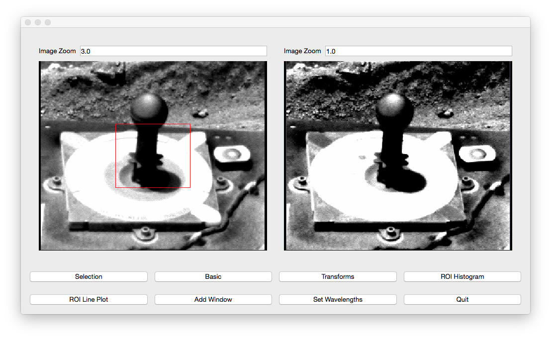
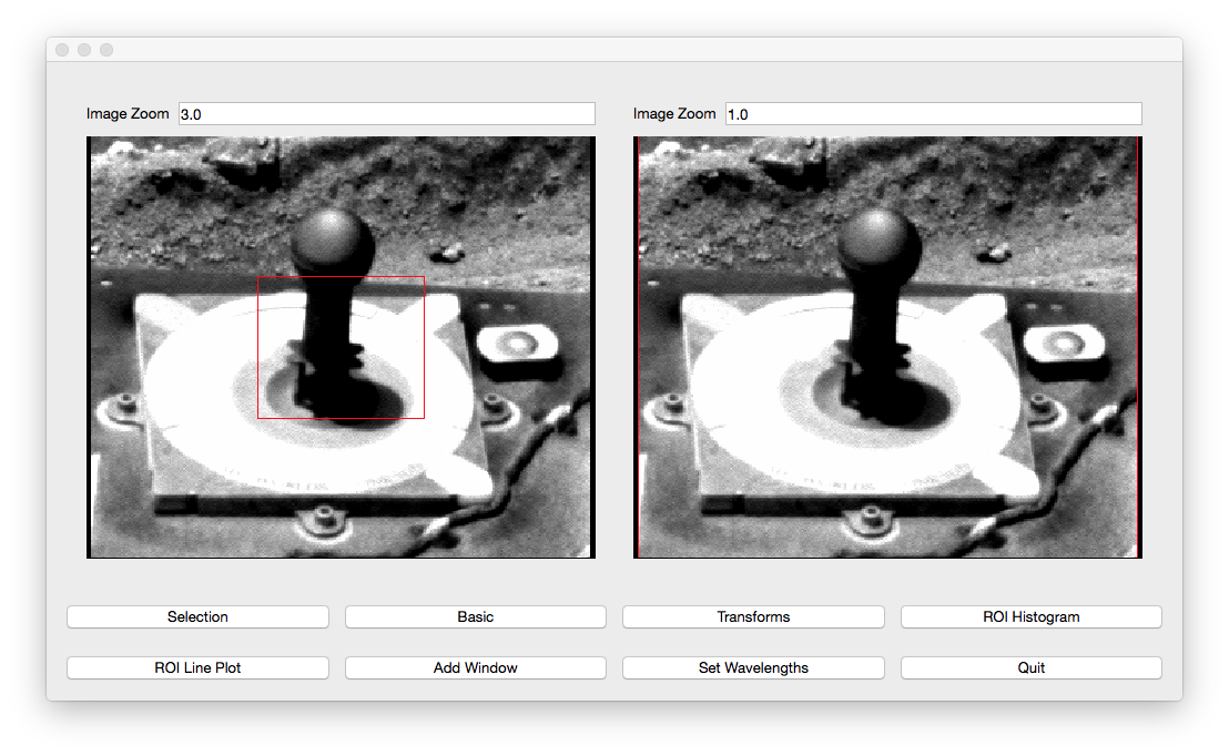
This will open the default window:
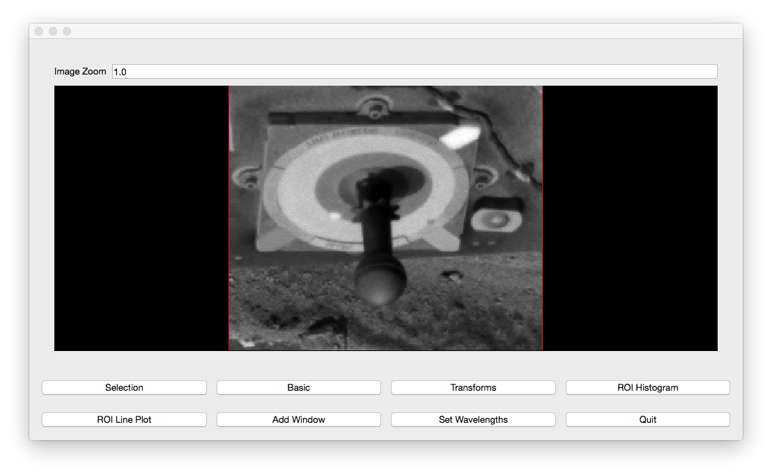

The bottom left window is considered the main window. In this window, the user
can adjust the position of the pan and open other windows. The bottom right
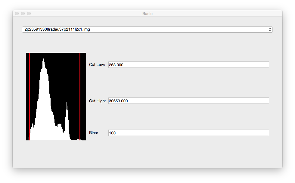
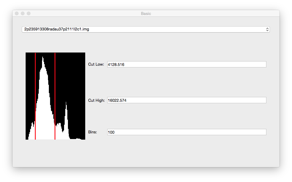
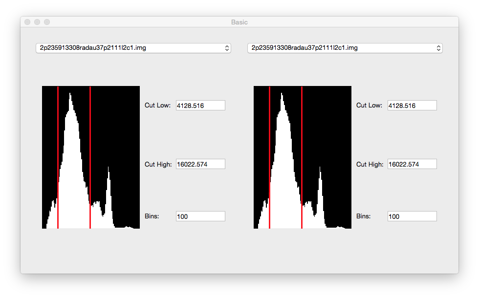
window is the basic window. Pressing the basic button will open this
window if closed. However, it starts out open. In this window, the user can
change the image in the views and adjust the cut levels by either moving the
red lines or typing in the numbers in the cut boxes:

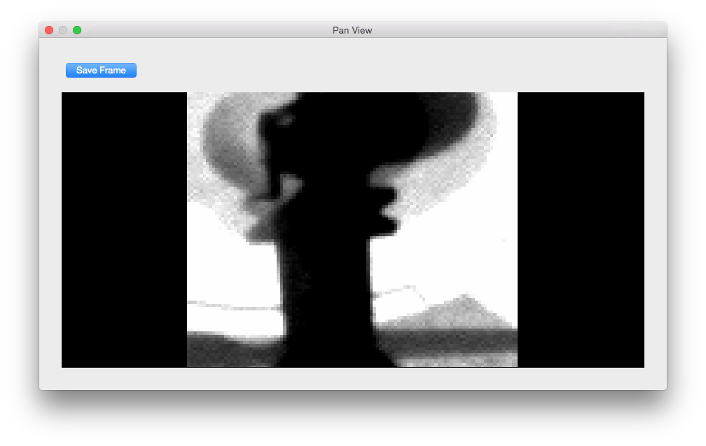
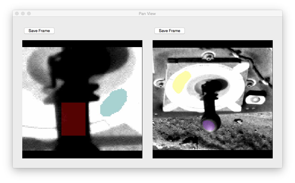
The top window is the pan window which displays the data in the main
window’s red box. The main function of this window is to make Region of
Interest (ROI) selections.
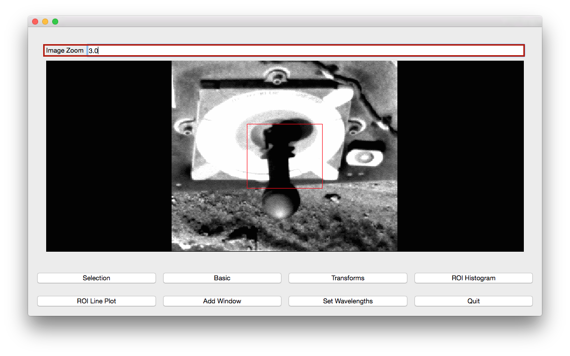
In the zoom box in the main window, the user can change the size of the box
and the data in the pan view:
the mouse wheel can also be used to change the zoom. Rolling the wheel foward
and backwards will adjust the zoom amount by +1 or -1 respectively.
The user can adjust the position of the box by clicking in the main window
where the center of the pan should be. Using the arrow keys will also adjust
the position of the box by 1 in the direction of the arrow key.
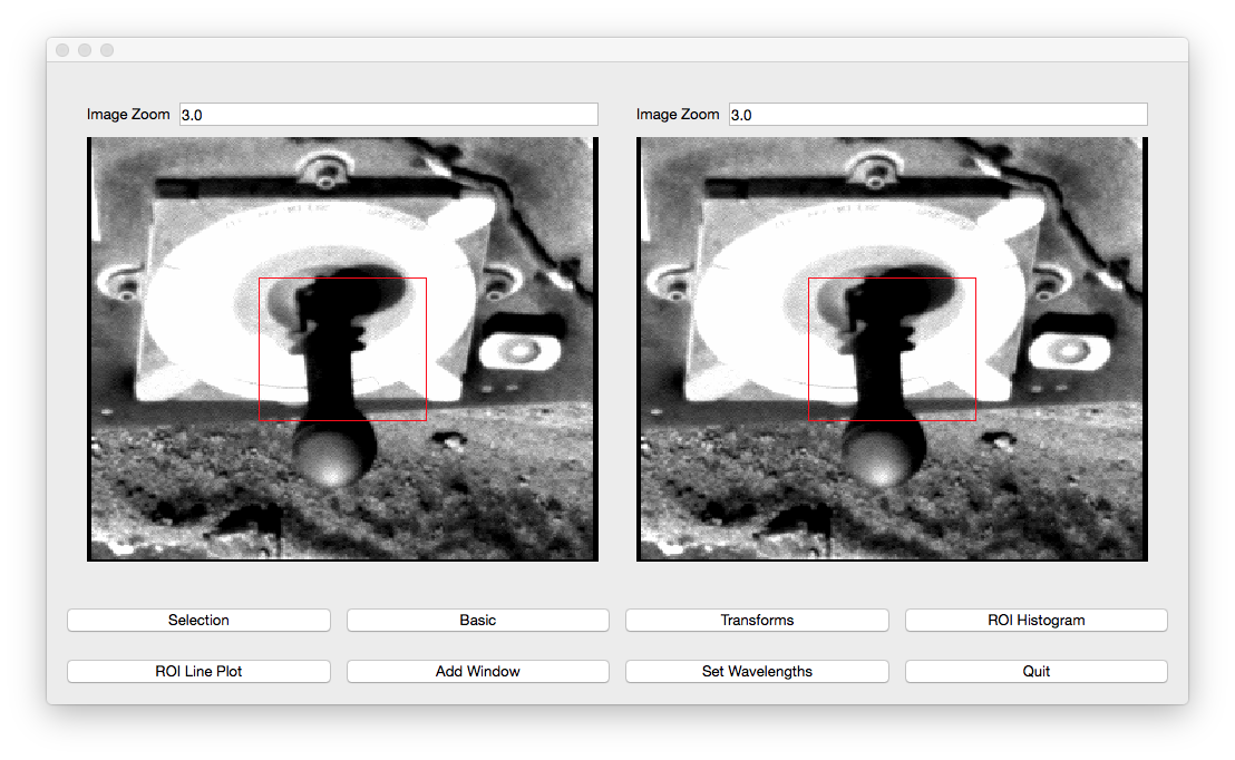
Clicking the Add Window button will open another view. This view will have
the same image, cut levels, and zoom by default.
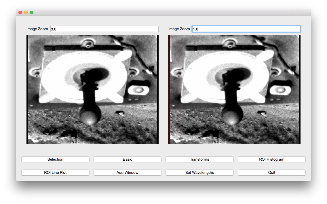
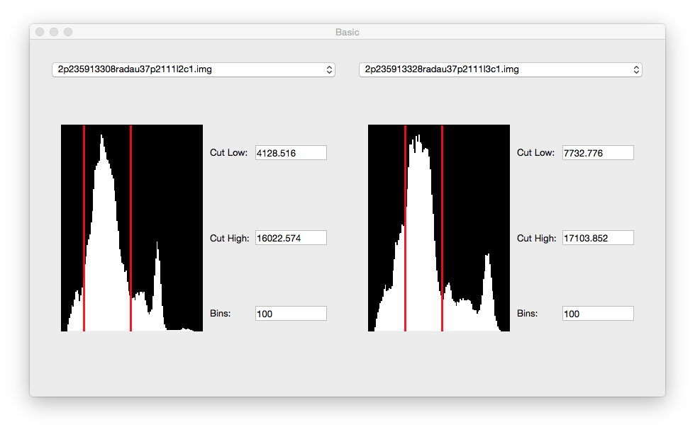
If the image’s are the same, chaning the cut levels on one image will automatically change the cut levels on another image. However, one can change the zoom on one view without changing the zoom another view.
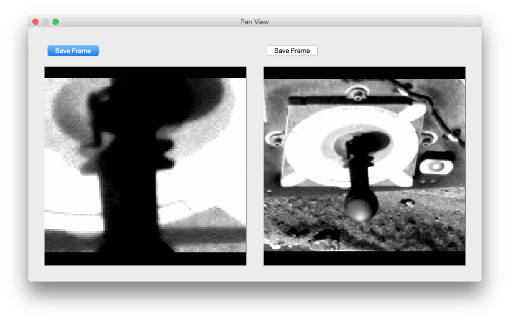
When the images are different, adjusting the cut levels on one image will only change the cut levels on that image:
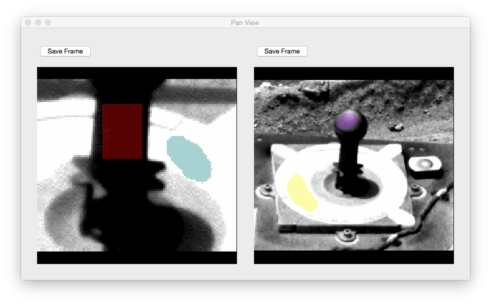
The user can create separate ROIs in each view:
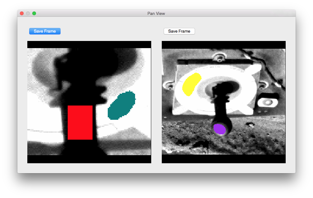
Clicking the Selection button will open the Selections Window:
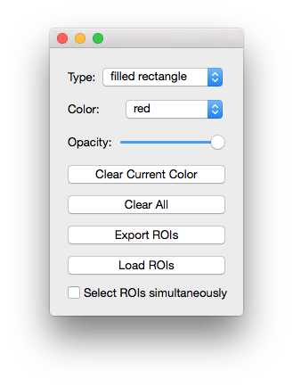
In this window, the user can choose the color of the ROI. The possible choices
for colors: red, brown, lightblue, lightcyan, darkgreen,
yellow, pink, teal, goldenrod, sienna, darkblue,
crimson, maroon, purple, and eraser (black). The selection type
can be changed in this window as well. The possible types are filled
rectangle, filled polygon, and pencil (single points).
Furthermore, in this window, the user can clear the current color or clear all
ROIs. Most importantly, the user can export ROIs to .npz files. These files
contain boolean masks and of the images and a list of files open at the time
of export. The ROIs in the 2nd, 3rd, 4th, etc. views will be labeled as
color#view while the ROIs in the first view is still labeled as color.
For example, to see the data in an example file example.npz, use numpy
load method
to view and utilize data.
>>> import numpy as np
>>> selections = np.load('example.npz')
>>> selections['red'][114:118, 142:146]
array([[ True,  True,  True,  True],
       [ True,  True,  True,  True],
       [ True,  True,  True,  True],
       [ True,  True,  True,  True]], dtype=bool)
>>> selections['purple2'][48:52, 146:150]
array([[False, False, False, False],
       [False,  True,  True,  True],
       [ True,  True,  True,  True],
       [ True,  True,  True,  True]], dtype=bool)
The user can also import ROI selections. However the images that are open must
be in the files list in the .npz file.
Changing the opacity in the Selecitons window will change the opacity on all the ROIs in every view:

You can view the data within the ROIs with the ROI Histogram window. Open
the window by pressing the ROI Histogram button in the main viewer.
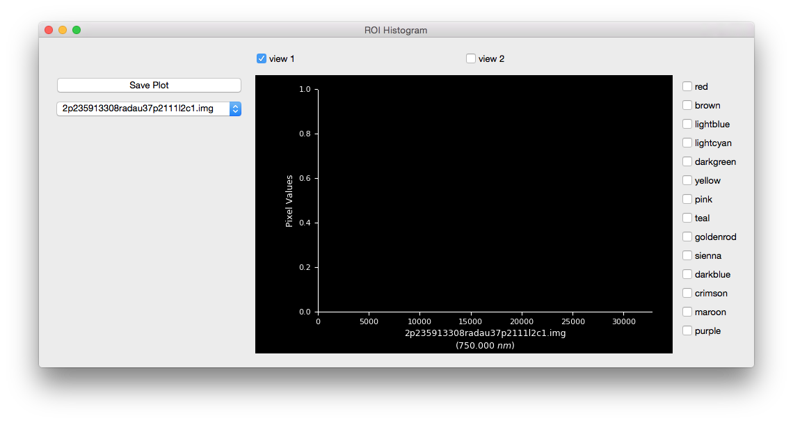
Display the data in the ROI by color by checking the checkbox next to the color. When the image in the menu and the current image in the checked view are the same, the plot will be a histogram:
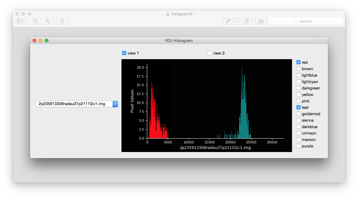
When the menu and the current image are different, the plot will compare the data:
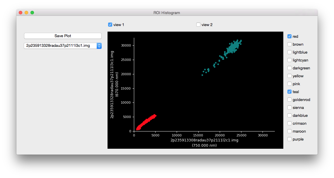
To view the data in the other view, check the view number:
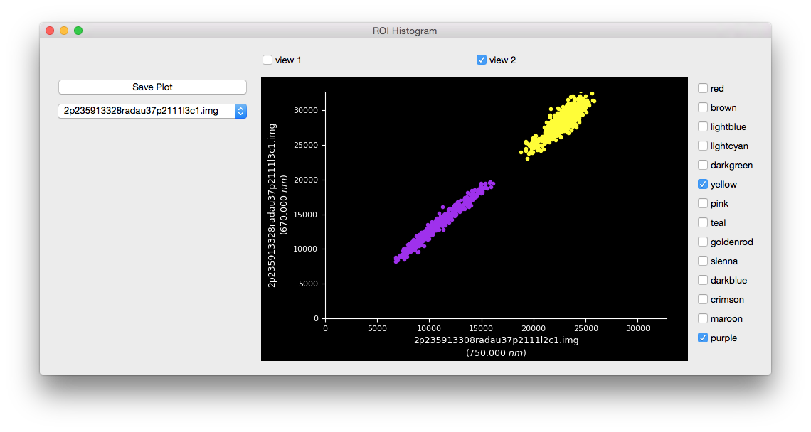
Overlay ROIs by checking other boxes. The order (depth) of the histogram data will be in the order that the user checks the boxes (i.e., checking red and then purple will result in purple overlaying the red).
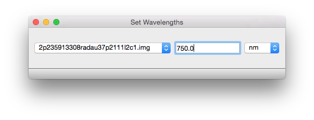
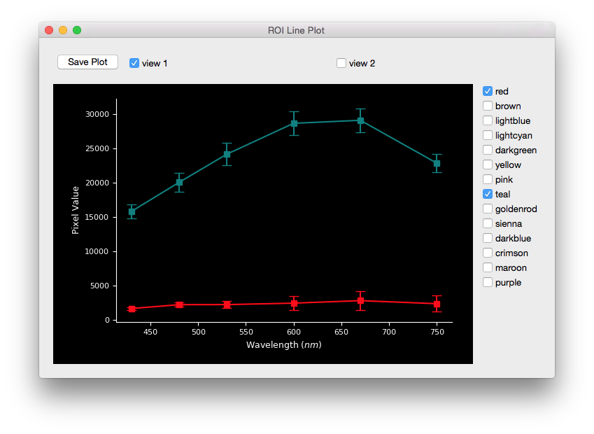
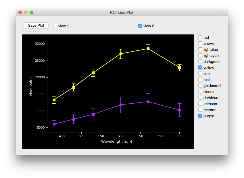
To perform multispectral analysis use ROI Line Plot.
If analyzing images that are not fully supported (see here for list of
instruments supported by pdsspect) the user must
manually input the image wavelength with Set Wavelength widget:
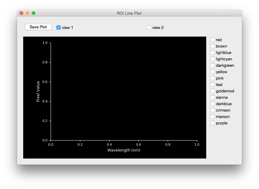
ROI Line Plot works similar to that of the histogram plot except it will
compare each image with an associated wavelength.
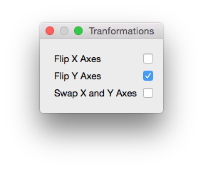
The user can flip the image over different axis with the Transforms window. The transformation will apply to each image in all the views:
Note that when opening multiple images at the same time, it is best practice
that they are all the same shape. Otherwise the images will have the smallest
common shape and not look as expected (i.e., If when loading two images where
one image has a shape of (63, 36) and the other image has a shape of
(24, 42), the displayed shape will be (24, 36). This will cause the
first image to have the right side cut off and the second image to have the
top cut off). This is done so all ROIs created can apply to the entire list
of images. To avoid this behavior, either only open images that have the same
shape or open images one at a time.
Supported Instruments
- MER
- Pancam
- MSL
- Mastcam
- Cassini
- Imaging Science Subsystem (ISS)
Adding More Instruments
We welcome anyone to create more models for instruments that are not yet supported. Please follow the Pull Request guide to make sure your model is compatible with the rest of the models. See Pull Request #20 as an example.
Pull Request Checklist
Please include the following checklist in your PR so we know you have completed each step:
- [ ] Created model as subclass of [InstrumentBase](https://github.com/planetarypy/pdsspect/blob/master/instrument_models/instrument.py#L7)
- [ ] Added model to [get_wavelength](https://github.com/planetarypy/pdsspect/blob/master/instrument_models/get_wavelength.py)
- [ ] Documented Model
- [ ] Tested Model
- [ ] Added model to [test_get_wavelength](https://github.com/planetarypy/pdsspect/blob/master/tests/test_get_wavelength.py) test
- [ ] Added instrument to supported_instruments.rst list
Style
- Set PR label to
Instrument Model - If an issue was created, please include
Fixes #<issue_number>at the top of the PR to automatically close the issue - Please include a link to any documents used to find the filter wavelength. Follow the example for Mastcam and/or Pancam
- When documenting your model, use numpy docs.See these examples. Also add to instrument_models.rst following the format of the other models
- For tests, if one of the core mission_data images is not from your instrument, create a minimal label in the tests\__init__.py. You must test the model itself and test that it works in test_get_wavelength
- Add the mission and instrument to the
supported_instruments.rstfile following the set format.